The Complete Tutorial on Using AutoCAD for Design Projects
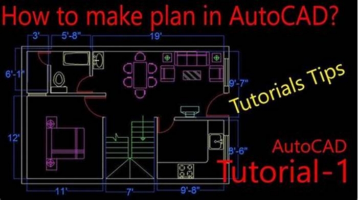
Getting started with AutoCAD
You can create a lot of different types of geometric objects in AutoCAD, but you only need to know a few of them for most 2D drawings.
Tip:If you want to simplify the display while you create geometric objects, press F12 to turn off dynamic input.
Lines
The line is the most basic and common object in AutoCAD drawings. To draw a line, click the Line tool.
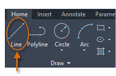
Alternatively, you can type LINE or just L in the Command window, and then press Enter or the Spacebar.
Notice the prompt in the Command window for a point location.

To specify the starting point for this line, you would type in the Cartesian coordinates 0,0. It's generally a good idea to locate one corner of your model at 0,0, which is called the origin point. To locate additional points, you could specify additionalX,Ycoordinate locations in the drawing area, however more efficient methods for specifying points are available, and will be presented in the Precision topic.
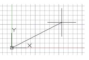
After you specify the next point, the LINE command automatically repeats itself, and it keeps prompting you for additional points. Press Enter or the Spacebar to end the sequence.
Grid Display
Some people like working with grid lines as a reference, while others prefer working in a blank area. To turn off the grid display, press F7. Even with the grid turned off, you can force your cursor to snap to grid increments by pressing F9.
Lines as Construction Aids
Lines can serve as reference and construction geometry such as
- Property line setbacks
- The mirror line of a symmetrical mechanical part
- Clearance lines to avoid interferences
- Traversal path lines
Circles
The default option of the CIRCLE command requires you to specify a center point and a radius.
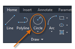
Additional circle options are available from the drop-down:
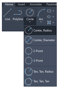
Alternatively, you can enter CIRCLE or just C in the Command window and click to choose an option. If you do, you can specify a center point, or you can click one of the highlighted command options as shown below.

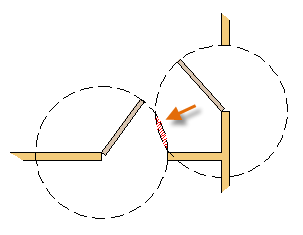
Circles can be useful as reference geometry. For example, you can see that the two doors in the illustration can interfere with each other.
Polylines and Rectangles
A polyline is a connected sequence of line or arc segments that is created as a single object.
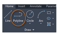
Use the PLINE command to create open or closed polylines for
- Geometry that needs to have fixed-width segments
- Continuous paths for which you need to know the total length
- Contour lines for topographic maps and isobaric data
- Wiring diagrams and traces on printed circuit boards
- Process and piping diagrams
Polylines can have a constantwidthor they can have different starting and ending widths. After you specify the first point of the polyline, you can use the Width option to specify the width of all subsequently created segments. You can change the width value at any time, even as you create new segments.

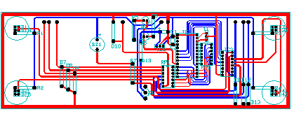
Here is an example of a printed circuit board in which the traces were created with wide polylines. The landing pads were created with the DONUT command.
Polylines can have different starting and ending widths for each segment as shown here:

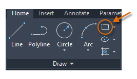
A fast way to create closed rectangular polylines is to use the RECTANG command (enter REC in the Command window).
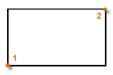
Simply click two diagonal points for the rectangle as illustrated. If you use this method, turn on grid snap (F9) for precision.
The User Coordinate System (Optional)
The user coordinate system (UCS) icon indicates the direction of the positive X and Y axis for any coordinates that you enter, and it also defines the horizontal and vertical directions in a drawing. In some 2D drawings, it can be convenient to click and place the UCS to change the origin point and the X or Y axis.
For example, by reorienting the UCS, you can create rectangles that are automatically aligned with the X axis as shown.
To restore the user coordinate system to its original location, enter UCS in the Command window and press Enter to specify the default <World> option.
Hatches and Fills
In AutoCAD, a hatch is a single, compound object that covers a specified area with a pattern of lines, dots, shapes, a solid fill color, or a gradient fill.
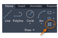
When you start the HATCH command, the ribbon temporarily displays the Hatch Creation tab. On this tab, you can choose from more than 70 industry-standard imperial and ISO hatch patterns, along with many specialized options.
The simplest procedure is to choose a hatch pattern and scale from theribbon, andclick within any area that is completely enclosed by objects. You need to specify the scale factor for the hatch to control its size and spacing.
After you create a hatch, you can move the bounding objects to adjust the hatch area, or you can delete one or more of the bounding objects to create partially bounded hatches:
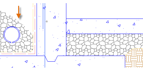
Tip:If you set a hatch pattern to be a solid or gradient fill, also consider setting a transparency level on the Hatch Creation tab for interesting overlap effects.
Here are some examples of how you can use solid-fill hatches:
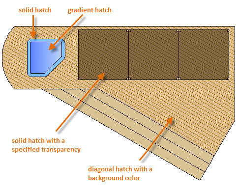
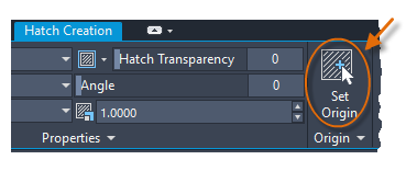
Tip:If you need to align the pattern in a hatch, which might be the case with the decking boards above, use the Set Origin option to specify an alignment point.
For overlapping hatches, fills, wide polylines, and text objects, use the DRAWORDER command to determine which objects are on top or below the others. For example, you probably want the yellow highway to cross the blue river rather than the other way around.

You can access several draworderoptions from the Modify panel on the ribbon. Click to expand the Modify panel, and then click the down-arrow as shown below.
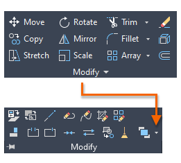
The drop-down list displays options for selected objects plus additional options that apply to all objects of a certain type, such as text.
Draw. Imagine. Create.
Autocad P&ID Tutorial For Beginners
Autocad P&ID (Piping and Instrumentation Diagrams) is a powerful software tool used by professionals in the engineering and design industry. Whether you are a beginner or have some experience with Autocad, this tutorial will guide you step-by-step, helping you understand the basics and get started with Autocad P&ID. In this blog post, we will cover the essential features and functionalities of Autocad P&ID, providing you with a solid foundation to create accurate and efficient Piping and Instrumentation Diagrams.
I. Understanding Autocad P&ID:
Autocad P&ID is a specialized software application built on the powerful Autocad platform. It is designed specifically for creating and editing Piping and Instrumentation Diagrams, which are crucial in the design and construction of industrial processes and systems. This software offers a range of tools and features that simplify the process of creating, managing, and collaborating on P&ID projects.
II. Getting Started with Autocad P&ID:
To begin using Autocad P&ID, you first need to install the software and set up your workspace. Once installed, launch the application and familiarize yourself with the user interface. Autocad P&ID offers a customizable workspace, allowing you to arrange panels, toolbars, and commands according to your preferences. Spend some time exploring the different menus and tool palettes to understand the available tools and their functions.
III. Creating a New P&ID Project:
To create a new P&ID project, go to the File menu and select New. Autocad P&ID provides various templates and sample projects to choose from, making it easier to start your design. Select the appropriate template based on your project requirements and customize it as needed. The software provides a comprehensive library of symbols and elements commonly used in P&ID drawings, allowing you to drag and drop them onto your canvas.
IV. Drawing and Editing P&ID Elements:
Once you have set up your project, you can start drawing and editing P&ID elements. Autocad P&ID offers a range of tools for creating and modifying pipes, valves, pumps, instruments, and other components. You can use the drawing tools to create lines and shapes, and then associate them with specific P&ID elements from the extensive symbol library. The software also allows you to add annotations, labels, and dimensions to enhance the clarity and understanding of your diagrams.
V. Collaboration and Documentation:
Autocad P&ID facilitates collaboration and documentation throughout the project lifecycle. You can easily share your P&ID drawings with team members, clients, or other stakeholders by exporting them in various file formats, such as PDF or DWG. The software also enables you to generate reports, including bill of materials, equipment lists, and instrument indexes, which are essential for procurement and construction purposes. Autocad P&ID ensures the accuracy and consistency of your drawings by automatically updating them when changes are made to referenced components.
Conclusion:
Autocad P&ID is an invaluable tool for professionals involved in the design and construction of industrial processes. This tutorial has provided you with a brief overview of Autocad P&ID and its essential features. By following the steps outlined in this tutorial, you can confidently create accurate and professional-grade Piping and Instrumentation Diagrams. Whether you are a beginner or have some experience with Autocad, Autocad P&ID offers a user-friendly interface and comprehensive toolset to support your design needs. So, why wait? Get started with Autocad P&ID today and unlock its full potential!
We hope this tutorial has been helpful to you. If you have any questions or would like to share your experience with Autocad P&ID, we invite you to leave a comment below. Lets continue the conversation and support each other in mastering this powerful software tool. Happy designing!
Autocad P&Id Tutorial For Beginners
Autocad P&Id Tutorial AutoCAD P ID and Plant 3D Technologies | Autodesk Developer AutoCAD P ID software allows you to create modify and manage schematic piping and instrumentation diagrams. AutoCAD Plant 3D adds 3D models /a /p /p ! /wp:paragraph /div ! /wp:group ! wp:group d drawspaces.com
Autocad Beginners Tutorial Pdf
AutoCAD Tutorial Pdf for beginners to learn AutoCAD Here you will find AutoCAD tutorial in Pdf for beginners to learn AutoCAD basics to advance. These are step by step tutorials. cadin360.com AutoCAD 3D exercises pdf for Mechanical Engineering Free Autocad mechanical practice drawings pdf drawspaces.com
Autocad P&Id Tutorial Pdf
Autocad P&Id Tutorial Pdf AutoCAD P ID and Plant 3D Technologies | Autodesk Developer AutoCAD P ID software allows you to create modify and manage schematic piping and instrumentation diagrams. AutoCAD Plant 3D adds 3D models /a /p /p ! /wp:paragraph /div ! /wp:group ! wp:group drawspaces.com
AutoCAD Plant 3D and P&ID | Autodesk Platform Services
AutoCAD P&ID software allows you to create, modify, and manage schematic piping and instrumentation diagrams. AutoCAD Plant 3D adds 3D models, including piping, aps.autodesk.com
Autocad Tutorial For Mac
Autocad Tutorial For Mac Beginner Tutorials for AutoCAD for Mac | AutoCAD for Mac Dec 3 2019 Additionally their are numerous tutorials available on YouTube available to assist in getting started with AutoCAD for the Mac:. knowledge.autodesk.com AutoCAD for Mac Online Training Courses | Linke drawspaces.com
Autocad 2007 Tutorial For Civil Engineers
Autocad 2007 Tutorial For Civil Engineers autocad 2007 tutorial for civil engineers YouTube Jan 26 2019 autocad 2007 tutorial for civil engineershttps://www.fiverr.com/olivia3d/3d-rendering-architectural-interior-and-exterior-designI Will www.youtube.com https://www.youtube.com/watch?v=FA8 drawspaces.com
Tutorial For Autocad 3D
Autocad Tutorials 3D Autocad 3D Complete tutorial for beginners YouTube Aug 9 2020 Open playlist: Autocad in 3D tutorials and exerciseshttps://youtube.com/playlist?list=PLe_I-JWckL7HOx1Ft6AdoZVUyVepxDnf4In this video you www.youtube.com https://www.youtube.com/watch?v=y41ZgOdExOo AutoC drawspaces.com
Tutorial For Autocad 2018
Tutorial For Autocad 2018 AutoCAD 2018 Tutorial for Beginners [+General Overview Mar 22 2017 Get into a new Way of Learning AutoCAD 2018 by Autodesk. AutoCAD 2018 getting started basics. MORE at https://theskillsfactory.com/Full www.youtube.com https://www.youtube.com/watch?v=KVci0xxUQ drawspaces.com
How To Use Autocad For Beginners
How To Use Autocad For Beginners AutoCAD Basic Tutorial for Beginners Part 1 of 3 YouTube Jun 20 2019 In this AutoCAD Tutorial for beginner video series you will learn about AutoCAD from scratch. Learn AutoCAD with full-length video courses www.youtube.com https://www.youtube.com/watch?v drawspaces.com
P&ID Software | AutoCAD Plant 3D | Autodesk
P&IDs are used to help design the layout of engineering process systems. The graphical diagrams include important information for installation or the systems www.autodesk.com
Blocks For Autocad Free Download
Blocks For Autocad Free Download: Unlocking Creativity in AutoCAD AutoCAD the leading computer-aided design (CAD) software has revolutionized the way architectural and engineering professionals work. With its extensive library of pre-designed blocks AutoCAD allows users to save time and enhance prod drawspaces.com
Draw Faces For Beginners
Draw Faces For Beginners Learn how to draw a face in 8 easy steps: Beginners Dec 7 2015 Learn how to draw a face in 8 easy steps: Beginners Step 1: Start with a circle Step 2: Draw guidelines on the face Step 3: Draw eyes in the /a /p ! /wp:paragraph /div ! /wp:column ! wp: drawspaces.com
Solved: autocad lt 2012 hangs after using ctrl + p Autodesk
Apr 1, 2019 Solved: Hi, my AutoCad LT 2012 hangs after using ctrl+p. It started when I have instaled it on may new computer. forums.autodesk.com
How to use a customized profile with the /p startup switch in AutoCAD
How to launch AutoCAD and have it load a custom profile. To have the customized profile available in a new Windows account: Start AutoCAD for the first time www.autodesk.com
How change system shortcut select previous p? AutoCAD
Jan 21, 2020 You can assign p to shortcut such as crtl+a, shifr+ctrl+a or alt+ctrl+a or to F* key. Also can be assigned to a mouse button or some forums.autodesk.com
AutoCAD 2024 Help | vl-vlx-loaded-p (AutoLISP) | Autodesk
vl-vlx-loaded-p (AutoLISP). Determines whether a separate-namespace VLX is currently loaded. Supported Platforms: Windows, Mac OS, and Web. Signature. help.autodesk.com
Solved: P and ID Symbol Library Autodesk Community AutoCAD
Mar 16, 2017 Solved: Can anyone help, Im looking for a recommendation for a symbol library for P&ID symbols, pipelines, electrical, etc. for ACAD 16. forums.autodesk.com
AutoCAD LT 2024 Help | P Functions Reference (AutoLISP) | Autodesk
P Functions Reference (AutoLISP). These AutoLISP functions all start with P. Functions. polar. Returns the UCS 3D point at help.autodesk.com
AutoCAD 2019.1.2 P.162.0.0 closing if double click to the [ A] Menu
Jan 2, 2019 Hi, I installed two times AutoCAD 2019 via the network deployment I created for the labs. AutoCAD start no problem but if by mistake I forums.autodesk.com
AutoCAD 2024 Help | vlr-pers-p (AutoLISP/ActiveX) | Autodesk
vlr-pers-p (AutoLISP/ActiveX). Determines whether a reactor is persistent. Supported Platforms: Windows only; not available on Mac OS or Web. Signature. help.autodesk.com

